× Altair Inspire Form 2022.0 Close
Altair Inspire Form 2022.0 | 2.8 Gb
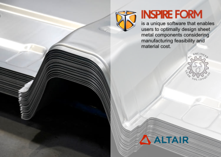
The Altair Engineering development team is pleased to announce the availability of Inspire Form 2022.0.0 is a unique software that enables users to optimally design sheet metal components considering manufacturing feasibility and material cost.
New Features and Enhancements 2022.0.0. The Inspire Form 2022 release includes the following new features and enhancements.
Dark Theme
Dark Theme is now supported throughout Inspire. You can change the theme in the Preferences under Workspace > Theme.. You can change the theme in the Preferences under Workspace > Theme
× Altair Inspire Form 2022.0 Close
Advanced Screen Capture
Several new features have been added to the settings for the Advanced Screen Capture feature available in the File menu. These include the ability to copy an image to the clipboard, as well as options to either show a file save dialog or save files to a default location. These options can also be accessed from the Preferences
× Altair Inspire Form 2022.0 Close
Geometry
Keyboard Shortcuts for Sketching
When outside of sketch editing mode, you can now press the S key and select a face to create a new sketch. Once in sketch mode, you can quickly access the most commonly used sketch tools with the following shortcut keys:
× Altair Inspire Form 2022.0 Close
New Pipe Tool
You can now turn lines and edges into a pipe. The pipe has a uniform cross section that can be circular, square, rectangular, or triangular.
New Slice Tool
In addition to slicing a part with a cutting plane, you can now slice a part with a surface. The surface must at least partially intersect the part.
New Intersect Surfaces Tool
You can now retain only the intersecting portions of one or more parts. This is a "smart" intersect tool that automatically deletes excess faces, edges, and vertices.
Extrude Tool Updates
The Extrude tool has been enhanced for this release. You can now extrude all types of profiles, as well as 2D surfaces in one or two directions, to create solids or 3D surfaces with optional end caps. In addition, you can now extrude in a custom direction by either (1) selecting a reference geometry to which you want to align the extruded shape or (2) freely orienting the extruded shape by dragging the curved arrow or entering an angle in the microdialog.
Pattern Tool Updates
The Pattern tool has been enhanced and now allows you to perform Boolean operations on the results, as well as merging with all or selected parts. In addition, the new Copies to Skip option allows you to select copies to exclude from the pattern. For linear patterns, selecting the Seed Only checkbox will restrict the pattern to the first row and column.
Draft Tool Updates
You can now add draft to one or more faces of a part when designing a product that is manufactured using injection molding.
Additional Changes and Enhancements for Geometry
- The workflow for the Boolean Combine tool has been updated.
- Performance improvements for import of CAD files.
- Inspire now supports the following file format versions for import:
× Altair Inspire Form 2022.0 Close
Feasibility
New Extend Tool
Extend surface edges naturally or linearly to introduce an addendum to a part before feasibility analysis.
Remove Tool
The Flange tool has been renamed to the Remove tool. You can either remove or partition a selected surface from the part.
New Unflange Tool
Open linear bends as well as flange surfaces on user-defined reference surfaces.
Trim Angle Analysis
Analyze the trim angle of the free edges of the part with reference to the draw direction using the Show/Hide Trim Angle context menu.
Part Edge Analysis
Analyze part edge movements during forming using the Tracer tool. The initial point of contact of the selected edge is shown along with the final point and a measure of minimum and maximum distance between them on the part surface.
Tryout
Forming Using Solids
Perform a single or multistage forming simulation with sheet metal modeled as solid elements like shells for a single blank only. The initial blank definition needs to be solid geometry. The materials in the database are updated to be compatible with solids. The workflows for model setup, analysis, and results visualization with shells are the same as for sheets. An FLD (Forming Limit Diagram) based on formability is also available for solid top and bottom surfaces.
Tool Creation By Offset
Create tools by offsetting with a value smaller than the sheet thickness. An offset value no smaller than a quarter of the sheet thickness is recommended. This is available only for forming shell elements.
Auto Gravity Model Setup
Quickly add a gravity operation and automatically set up the tools before a forming operation using the Add Gravity option in the operation context menu. This will automatically copy bottom tools and pins from the forming operation to the gravity operation to reduce setup effort.
Trim Operation
You can now select the surface - Top, Middle, or Bottom - from which the trim/pierce/lance line is extracted to improve trimming robustness. Geometry edges can now be selected for trim/pierce/lance objects
Trim Angle Analysis
Analyze the trim angle of the free edges of the part with reference to the draw direction using the Show/Hide Trim Angle in the context menu.
Part Replace
Replace any tool or blank, except for drawbeads, with a part in the model or from a file. The replaced part is deleted from the session.
Tool Mesh Parameter Option
New options to select Individual tools or All tools for the tool mesh parameter have been added to the Preferences. This setting determines the mesh parameters for the tool meshing. Individual tools were used in past releases, and this is the default.
Predict
Select geometry edges for blank shape and trim line prediction.
Springback Compensation.
Export springback compensation data (point cloud and deformation vector) in a text file format supported by CATIA and UGNX. This enhancement allows data exchange with CAD software to perform geometry based springback compensation. The springback compensation distance contour sign can now be flipped with a new result type.
Edge Strain
Contour edge strain can now be applied on free edges of the blank to study potential failure due to edge fracture.
Auto Callouts
Automatically create callouts based on Max (upper limit) and/or Min (lower limit) value. One callout per iso contour zone is created.
Tracers – Draw-in
Select a reference step to measure draw-in more accurately. By default, the first step is used as reference, but now it can be changed to any step, preferably to the end of binder close for apt comparison with physical tryout results. The draw-in measure dynamically updates with the animation
Additional Changes and Enhancements for Forming
- Material: Barlat yield criteria can now be selected for Yoshida hardening law.
- An edge or line body can now be selected to define the draw direction.
- Orientation angle and center output are now included in blank nesting reports.
- Trim angle contour is now automatically enabled at blank fit and nesting to facilitate the best orientation selection for lock rotation nesting mode.
× Altair Inspire Form 2022.0 Close
Altair Inspire Form is a complete stamping simulation environment that can effectively be used by product designers and process engineers to optimize designs, simulate robust manufacturing and reduce material costs. With the fast and easy feasibility module, users can analyze parts in seconds to predict formability early in the product development cycle. The automated blank nesting proposes an efficient layout of the flattened blank on the sheet coil to maximize material utilization. The tryout module includes a highly scalable incremental solver, helping users to iterate and simulate multi-stage forming, trimming and springback in a modern and intuitive user interface, reducing complexity and making the production of high quality parts more economical.
Altair Inspire Form also offers an innovative user experience to seamlessly transition between design and analysis through a highly intuitive user interface designed for beginners and experts alike. It enables part and process designers to evaluate manufacturability early in the development cycle to avoid costly trials downstream. Altair Inspire Form automatically generates a report for fitted and nested blanks to help maximize material utilization
Altair Inspire Form Tryout - Manual Setup
This quick video tutorial shows how to perform a manual setup in the tryout (incremental analysis) workflow.
Altair is a global technology company that provides software and cloud solutions in the areas of product development, high performance computing (HPC) and data analytics. Altair enables organizations across broad industry segments to compete more effectively in a connected world while creating a more sustainable future.
Product: Altair Inspire Form
Version: 2022.0.0 Build 4144
Supported Architectures: x64
Website Home Page : www.altair.com
Languages Supported: english
System Requirements: Windows *
Size: 2.8 Gb
* System Requirements: × Altair Inspire Form 2022.0 Close
Please visit my blog
Added by 3% of the overall size of the archive of information for the restoration
No mirrors please
× Altair Inspire Form 2022.0 Close
Download File Size:2.65 GB