× AVL Simulation Suite 2023 R1 Close
AVL Simulation Suite 2023 R1 | 9.1 Gb
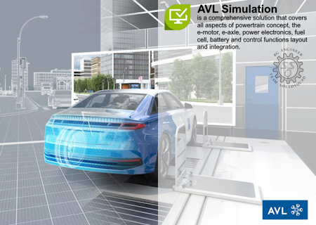
The software developer Advanced Simulation Technologies (AST) is pleased to announce the availability of AVL Simulation Suite 2023 R1 is a comprehensive solution that covers all aspects of powertrain concept, the e-motor, e-axle, power electronics, fuel cell, battery and control functions layout and integration.
Release 2023 R1
We are pleased to announce the latest software releases for the following solutions:
Release 2023 R1: Fuel Cell – Components and Systems × AVL Simulation Suite 2023 R1 Close
SOxC Model Generation
Wouldn't it be handy to have a running SOxC model with just a few clicks? CRUISE M now offers such a feature, allowing experienced modeling engineers to save time and enabling newcomers to easily begin with SOxC simulation based on nothing more than data from stack specification sheets. CRUISE M not only generates the model, you are also offered a tailored dashboard for online monitoring and online control, and you receive an offline result report directing you to the essential results characterizing the stack model. As an option, you can choose between internal reforming of CH4 and NH3 and you can also configure thermal conditioning, or you might like to step into the experienced user's settings and configure details on the electrochemistry and the spatial resolution of the stack model.
× AVL Simulation Suite 2023 R1 Close
SOxC Model Parameterization
Wouldn't it be time-saving to have a guided workflow to configure an SOxC stack model? CRUISE M's SOxC Generator makes it possible. It offers a stepwise process to identify parameters for the cell voltage or species conversion based on reference data. The workflow supports fuel cell and electrolyzer operation. In the first step, you provide either steady-state (i.e. classical polarization curves) or transient data over time. These reference data are meant to comprise information on current and voltage, air and fuel supply, inlet and outlet species fractions, pressures, etc. In a second step, you select the variation parameters, their initial and range values and you can optionally tweak the settings of our optimization method. In the third step, you click the "run optimization" button and you have time for a coffee. When the optimization is done, CRUISE M provides comparison plots on the initial, reference and optimized data and parity plots, giving a fast overview on the fit quality. The last step is to gen rate the model and to guide you to CRUISE M with a ready-to-run model parameterized to your data.
× AVL Simulation Suite 2023 R1 Close
PEMFC 1D Electrochemical Model
Detailed modeling of all electrochemical, transport and conversion phenomena in the MEA is key as it has a decisive influence on the overall stack performance. CRUISE M addresses this challenge with a new 1D electrochemical model in its fuel cell stack component. When selecting the new model, you have access to a broad list of functionalities:
- The gas diffusion layer (GDL) can be split into (sub-)layers featuring different material properties influencing the transport resistance for gases and liquids, enabling the consideration of the impact of microporous layers (MPL) on the cell/stack conversion efficiency.
- A liquid water transport model is made available, describing capillary transport in a physical-based manner, and considering local vapor pressure for the phase change between liquid and gas, allowing an in-depth analysis of cell-internal self-humidification phenomena.
- At the interface between GDL and channel, a dedicated film model takes care of the liquid transfer into the bulk flow of the channel. The transfer considers direct evaporation from the film, as well as the tear-off of liquid droplets that are further transported along with the gas flow, and thus enabling detailed assessment of macroscopic liquid water transport.
- The formation of ice in the membranes can be chosen to model its impact on the gas and liquid phase transport resistance. This is key when addressing fuel cell de-frosting processes and thus supports the assessment of different cold-start/freeze-start strategies.
- Species cross-diffusion is resolved in 1D via a multi-species model, offering a precise prediction of all transport phenomena influencing the stack dynamics at different frequencies.
× AVL Simulation Suite 2023 R1 Close
Each single functionality can be optionally selected. With that, you can activate all features in a stepwise manner, or you can pick only those that fit your application case.
Hydrogen Blower
Compressor performance maps are typically measured using air. The application of such maps can be a challenge when simulating hydrogen blowers as hydrogen features significantly different gas properties, potentially leading to an incorrect prediction of the compressor behavior. This version of CRUISE M overcomes this and allows for the more precise treatment of different feed gases at two different locations. In the TC Map Generator, you specify the properties of a reference gas (air is offered as default), in the compressor component itself, you can opt for a "gas composition specific performance map scaling". With this check box selected, any variation of the operating gas is taken into account for the evaluation of the corrected speed and mass flow. A comparison with experimental data shows an excellent match over a broad range of different hydrogen ratios in the feed gas.
Connected Oxidation and Reformer Catalysts
When modeling balance of plants (BoP) from solid oxide fuel cell (SOFC) systems, oxidation and reforming catalysts are often designed in a way that the heat from the exothermal exhaust oxidation is used to supply the heat required for reforming of the feed gas. For that purpose, catalysts are designed in a highly integrated manner to exchange heat typically in co- or counter-flow operation. This version of CRUISE M enables you to thermally connect catalyst components considering the 1D temperature and heat flow distribution over the length of the converters. The flexibility extends to 2D and 3D solid wall components often used in thermoregulation networks. If you want to study the basics of heat transfer, you can turn off the chemical reactions and obtain the familiar temperature profiles from heat exchangers operated in co- or counterflow.
Freeze Start of PEM Fuel Cells
For low temperature PEM fuel cells, it is now possible to calculate the freeze start from subzero temperatures. Ice formation and respective phase change processes in the porous media can hence be analyzed in fully space- and time-resolved details. With the current FIRE M version, water can exist in five different states in a PEM fuel cell, namely the gas, liquid and dissolved state, as well as the ice state and the frozen dissolved water state. Phase change models are available for the five states of water. To describe phase change in the porous media in a highly accurate manner, the so-called Gibbs-Thomson undercooling effect is included, representing the effect of wettability and pore size on the melting point.
× AVL Simulation Suite 2023 R1 Close
Release 2023 R1: Powertrain – Systems and Controls × AVL Simulation Suite 2023 R1 Close
Importing AVL CRUISE Models
Version 2023 R1 brings AVL CRUISE M and AVL CRUISE closer together. CRUISE models can now be loaded into CRUISE M, thus automating the entire process of model migration. Specifically, this means that identical components are mapped to new CRUISE M components. Deviating components are mapped to similar components or component groups. During the process, the entire connection topology is interpreted and a corresponding CRUISE M model network is built. Task folders and tasks from CRUISE are transferred to case sets and cases, subsystems are mapped to layers, and both are maintained in CRUISE M scenarios. If deviations occur that cannot be resolved by the software itself, a dedicated migration protocol guides you manually through the remaining steps.
× AVL Simulation Suite 2023 R1 Close
Inverter Loss - Detailed and Simple Model
The Dynamic E-Machine component provides the option of an internal inverter that models six ideal switches responding to an externally provided PWM signal. The approach allows the e-machine to be run on three phases considering three-phase details. This version of CRUISE M enables the behavior of inverter losses to be modeled one step closer to reality. Two inverter types are available, "IGBT with diode" and "MOSFET". CRUISE M maps the switching energies into power losses and uses them together with the conduction losses to calculate the corresponding current in the electrical network. All details on the losses are available on the data bus network and can be used for any kind of control purpose or for simple online analysis during a running simulation.
× AVL Simulation Suite 2023 R1 Close
FMU Export - FMI 3.0
The export of CRUISE M model FMUs is taken to the next level. This version enables models to be either exported according to the classic FMI 2.0 standard or CRUISE M FMUs can be generated according to the latest FMI 3.0 standard. The exported CRUISE M FMUs using the FMI 3.0 standard offer the same functional scope as the 2.0 standard. Beyond that, non-scalars of data type characteristics (i.e. two-column tables, y(x)) can now also be exported. Whenever a physical aspect is covered by a characteristic, it can be exposed and the table can be changed from the hosting environment without needing to return to CRUISE M's GUI.
× AVL Simulation Suite 2023 R1 Close
Model Data Compare
× AVL Simulation Suite 2023 R1 Close
Managing the data of different model versions is key to efficiently maintaining the progress of a model. This release provides a new and more rigorous diff functionality that works on the level of an entire project, comprising all models that are packed within the project, including configurations in the Simulations, Results, Optimization and Parameters tabs.
VLE Heat Exchanger - Parameterization Access
Air conditioning systems or heat pumps are essential parts of the vehicle thermal management system (VMTS) of battery electric vehicles. This version of CRUISE M increases the versatility when configuring different components of our VLE circuits. These are the MPET, Fin & Tube, Plate, Tube & Tube and Tube Heat Exchangers, as well as the VLE Pipe component. All these components offer the possibility of changing the constant inputs of heat and pressure drop correction factors to be variable via CRUISE M’s data bus network. These inputs, together with additional data bus outputs on mass flow, volume flow, etc., are the basis for performing component parameterization in a closed loop.
× AVL Simulation Suite 2023 R1 Close
Ph-Diagrams - Online Visualization
Ph-diagrams are a commonly used and very effective way of assessing the operating behavior of air conditioning or waste heat recovery systems. This version of CRUISE M provides the service of an online inspection of ph-diagrams during a running simulation. The online ph-diagram is given in a simplified format showing the saturation lines of the selected fluid and the operating lines (i.e. compression, condensation, expansion and evaporation) of all involved components.
× AVL Simulation Suite 2023 R1 Close
Release 2023 R1: Vehicle – ADAS/AD × AVL Simulation Suite 2023 R1 Close
The automotive industry is in a constant state of change and along with it your needs. To meet these needs, we at AVL are permanently working on the further development of our products and services to support you in fulfilling your daily tasks. The latest release of our simulation solution for development and virtual validation of automated and autonomous driving functions includes improved OpenSCENARIO standard coverage by AVL Scenario Designer and high-performance Simulation Platform powered by Model.CONNECT.
AVL Scenario Designer - Road Builder Add-On and Local Road Library
With the new Road Builder Add-On, users can quickly generate road segments in ASAM OpenDRIVE format. No tiresome manual editing needed – just choose from a list of available templates like curvy rural roads or highways with ramps. All templates are parametrizable allowing for a variation of road and scenario at the same time. This opens up limitless possibilities such as making scenarios suitable for different countries. The Local Road Library is a set of OpenDRIVE road networks that come automatically with the Scenario Designer installation. Boost your scenario creation capabilities by choosing a suitable road network instead of manually creating new roads.
× AVL Simulation Suite 2023 R1 Close
Esmini Interface for High-Performance ADAS/AD Controls Testing – Even on Your Notebook
When testing the control algorithms of automated driving systems, an object-based representation of the environment is sufficient. The focus is on decision making, path planning, and motion control. Esmini is a lightweight open-source tool that can execute scenarios in ASAM OpenSCENARIO standard with a very high performance. By integrating esmini into the Model.CONNECT co-simulation platform, you can easily setup your closed-loop test setup and define parameter variations. The built-in Job Management System (JMS) executes all the tests on your local machine. The optimal number of parallel simulations depends on your hardware. The simulations can be massively scaled in our distributed cloud computation cluster allowing you to execute millions of test cases overnight. Frequent testing is a crucial part of a successful agile development process for ADAS/AD systems. Using our Python API, you can easily integrate and fully automate the test execution in you CI/CD pipelines.
× AVL Simulation Suite 2023 R1 Close
Figure 2: Performance benchmark of an Adaptive Cruise Control System (ACC) test setup executed on a normal notebook
Release 2023 R1: Vehicle – Energy and Driving Attributes × AVL Simulation Suite 2023 R1 Close
The New AVL VSM Release Presents the 3rd Evolution of the Vehicle Model Factory (VMF)
This release enables the automatic identification of tyre parameters from road measurements. The new feature has been added to the already proven identification of weight distribution, driving losses, suspension, electric drive unit, HV battery, internal combustion engine, brakes and steering system parameters. Aiming to reduce time and costs during the development process, the VMF approach allows digital-twin creation using vehicle measurements and a minimum number of key parameters.
× AVL Simulation Suite 2023 R1 Close
New Features Related to AVL VSM Useability, Physics and Interfaces Are Available
Additional vehicle template databases from different classes and segments are included as examples. The release also includes support for custom 3D tracks, allowing users to add a unique visualization of roads and environments.
× AVL Simulation Suite 2023 R1 Close
× AVL Simulation Suite 2023 R1 Close
Driveability simulation of battery electric vehicles achieves high accuracy with a new elastic motor shaft model and improved control of torque build-up. Additionally, a multi-speed gearbox for each electric motor is now available. Automotive industry is steering efforts towards holistic product development; thus, this release is also part of AVL vSUITE. It is possible to use different VSM add-ons such as Commercial Vehicle and Tractors or High Performance and Lap Time.
× AVL Simulation Suite 2023 R1 Close
Release 2023 R1: Virtual Powertrain – Performance and Thermal × AVL Simulation Suite 2023 R1 Close
Highlights in AVL FIRE M
Multi-Component Flash Boiling for Injector and In-Cylinder Flow Simulations
Simulating the complete chain of events - from internal injection nozzle flow, fuel injection into the combustion chamber, generation of wall film, combustion and emission formation - is a challenging task which can now be performed significantly more conveniently thanks to FIRE M 2023 R1 while considering even more physics. All related simulations and simulation models access the extended Material Property Database enabling the handling of multi-component surrogate fuels (fossil resource based, e-, bio-, syn-fuels). Extensions of the fuel evaporation model take care of flash boiling, which occurs when injecting under elevated temperatures.
× AVL Simulation Suite 2023 R1 Close
Thermolysis and Hydrolysis Model in the AVL FIRE M Multiphase Framework
For diesel-powered vehicles, the emission of nitrogen oxides (NOx) is a particular challenge. This new release of FIRE M allows you to simulate the decomposition of the Urea-Water solution along with the activated General Gas Phase Reaction (GGPR) module considering that the thermolysis-hydrolysis process is happening simultaneously, in the multiphase framework This improves the predictiveness of the simulation solution.
Table Generation for ICE Combustion Simulations using ECFM-3Z
The tools needed for the generation of laminar flame speed and auto ignition delay tables have been packed into a GUI-driven workflow, which is made available with the release 2023 R1. The tables can be used directly for combustion simulation using the ECFM-3Z model of FIRE M.
× AVL Simulation Suite 2023 R1 Close
Further Highlights in AVL FIRE M 2023 R1
UI-based differencing of FAME projects: The 2023 R1 release of FAME takes the first step in making it easy for you to compare FAME projects utilizing the graphical user interface to visualize the differences.
Melting and solidification model: This new release models the mass transfer of a melting and solidification problem in the multiphase framework of FIRE M.
TABKIN table generation: Table generation is now available also under Windows.
1D/3D Coupling Interface: A FIRE M/GT Power (a product of GAMMA TECHNOLOGIES Inc.) interface is now available with FIRE M.
Highlights in AVL CRUISE M
Dual-Fuel and Gas Engine
The latest engine and engineering enhanced cylinder models enable the investigation of alternative fuels. It is possible to combust multiple fuels, to use gaseous fuels, and to change the fuel during a running simulation.
× AVL Simulation Suite 2023 R1 Close
Engineering Enhanced Cylinder Models
The engineering enhanced gasoline cylinder (EEGC) has been enhanced with new functionalities:
- The fuel treatment has been improved by utilizing the gas property generator to specify the fuel composition according to the fuel properties given by fuel specification sheets. This allows you to consider oxygenated gasoline fuels as well as various compositions of gaseous fuels in a more accurate manner.
- A new CNG combustion model has been introduced along with the improvement of the fuel treatment. The engine-out emission models are extended with a CNG-specific THC/CH4 sub-model. You can now choose between hydrocarbon emission models for gasoline or CNG combustion via a drop-down menu in the EEGC GUI.
- The cylinder component now offers the possibility to configure two different fuels (e.g. gasoline and CNG). You can select your fuel before starting a simulation and you also can switch between fuels during a simulation run. With that, you can tackle bi-fuel applications in SiL and HiL environments without having to restart your model.
The engineering enhanced diesel cylinder (EEDC) component has been further enhanced with additional models and parameters:
- In the fuel injection system you can now choose between two different types of injectors, giving more precision in predicting the injected fuel amount.
- The injection coordinator, which differentiates between the various pilot, main and post injections, can now be tuned with external parameters to improve its robustness.
- The friction model has been improved to consider the influence of the oil temperature during the warmup phase.
- A new model has been added to the EEDC to provide information about possible misfiring. The parameterization wizard has been further enhanced. It now allows the calibration of the peak cylinder temperature and the emissions of CO, THC and soot.
× AVL Simulation Suite 2023 R1 Close
Motored Combustion and Variable Compression Ratio
The Combustion Chamber component has been enhanced with two functions.
- Motored combustion: The combustion chamber can be operated without an actual combustion model. The intake of any gas, its compression and exhaust can be simulated in an isolated manner. With that, the behavior of reciprocating compressors can be mimicked.
- Variable compression ratio: The compression ratio can be actuated via a data bus channel. This enables investigating engine concepts.
× AVL Simulation Suite 2023 R1 Close
Release 2023 R1: Powertrain – Durability and NVH × AVL Simulation Suite 2023 R1 Close
Highlights in AVL EXCITE M
Rolling Element Bearings - Damping in Clearance Regime
For Rolling Element Bearings, in the currently applied approach, the material contacts accounts for damping while the damping which is expected in the clearance regime is not considered. To stabilize the bearing behaviour in the clearance region, additional damping forces is acting in the gap region of the individual contacts. The required damping coefficients are specified as a table depending on the contact approach distance.
× AVL Simulation Suite 2023 R1 Close
× AVL Simulation Suite 2023 R1 Close
The following graph shows the bearing radial displacement as the response to a bearing impact load. While the bearing without any clearance damping reveals repeated bouncing within the radial play, the variant with clearance damping is characterized by a smoother decay.
Deviation/Tolerance Input for Spline Gear Joint
Geometric deviations from nominal drawing dimensions may have a significant impact on the NVH performance of transmissions and Electric Drive Units. To consider deviations that cause eccentricity of components, the Spline Gear joint has been extended to process axial, radial and angular deviation inputs given at the shaft/hub link locations defining the body-spline profiles of the connection. The figure shows the impact of a radial deviation of the outer spline profile against the axis of rotation of a shaft. The radial hub motion follows the run-out of the shaft-spline leading to periodic position changes associated to radial force fluctuation in the spline-gear interface.
× AVL Simulation Suite 2023 R1 Close
Spline Gears: Offer Crowning via Microgeometry
For certain use cases of splined gears, it is essential that only the torque, but no bending moment is transferred from one shaft to another. This is achieved by applying a crowning modification to the flank surface across the width of the gear. Crowning can now be specified on the outer (shaft) and inner (hub) side of the spline gear contact. The modification is visualized in the 3D-viewer and IMPRESS M.
× AVL Simulation Suite 2023 R1 Close
× AVL Simulation Suite 2023 R1 Close
Cylindrical Gears: Offer Flank Surface Waviness Modification
Manufacturing of the gear grinding process cause various imperfections of the resulting flank surface which can have a significant impact on the gear noise. One prominent deviation pattern is called waviness. Waviness along the gear tooth can now be specified on cylindrical gears and is considered by the contact model.
New Method to Consider Localized Gear Wheel Body Node Deflections at Tooth Contact (Beta)
Advanced Cylindrical Gear Joint has been able to consider flexible gear wheel body deflections from circumferential nodes placed at the root of the teeth. However, the applied mapping method performs some averaging that causes specific gear wheel body deflection shapes (for instance the well-known "potato-chip" mode), not sufficiently reflected in the contact-load distribution between the individual teeth. A new mapping method that considers body deflections affected by the gear contact has been implemented optionally. Using this option, local body modes will influence the development of the gear contact pattern in a much more realistic way.
× AVL Simulation Suite 2023 R1 Close
New method is more prone to dynamic loss of flank contact and it is more sensitive to numerical instabilities of the time domain solution. Therefore, for 2023 R1 the feature is released as a beta version. To activate it select "Use local node deflections for tooth contact (Beta version)" check box in ACYG "Joint properties | Stiffness".
Pulse Width Modulator
Pulse Width Modulation (PWM) realizes the variable magnitude and variable frequency voltage demand calculated by the current controller. The pulses control the switches of the inverter. The pulsed voltage introduces considerably higher harmonics into the torque and the forces acting on the electric motor's stator and thus contributes to e-motor NVH. EXCITE M now makes it possible to investigate the effects of PWM to avoid tonal excitations in regard to PWM strategies, overmodulation, use of constant or a speed-dependent switching frequency or a band for a random switching frequency as sown in the figure.
× AVL Simulation Suite 2023 R1 Close
× AVL Simulation Suite 2023 R1 Close
Order Analysis for E-Motor Tooth Forces
Force excitation of the stator teeth in an electric motor is best described by waves propagating with and opposite to direction of rotation. Due to the nonlinearity of the magnetic field spatial wave numbers will occur at base and harmonic frequencies. The analysis of their amplitudes and phases provides valuable indicators for an acoustic analysis. 2D-order analysis is now provided for all electric motor models with circumferential link locations for the stator. Each linking section is evaluated separately, which allows the study of impact of skewing, eccentricity and tilting of the rotor. Impact of pulse-width modulation can also be captured by narrow-band analysis.
New Generic Speed Controller
A new generic speed controller component is introduced in EXCITE M. This speed controller replaces the internal speed controller of the Electric Machine Controller but is also available as a generic standalone component for other use cases. The controller is a PI-controller, where controller gains and initial states can be user-defined or automatically calculated based on control parameters (rise time and percentage overshoot), and model-specific parameters (effective moment of inertia and effective rotational damping). The controller is implemented as a specialized version of the compiled function component. Due to this approach, it is also possible to convert the speed controller to a regular compiled function component for custom modifications like changing signals, parameters or even the actual controller code.
× AVL Simulation Suite 2023 R1 Close
Direct MATLAB Interface
The MATLAB interface component enables a co-simulation between EXCITE M and MATLAB®/Simulink®. The interface is fully integrated into the signal network, allowing connections to sensors, functions (compiled function, tables, etc.), load applicators or other interfaces. Input and output signals can be defined for arbitrary physical quantities and additional parameters for the Simulink® model. Currently, MATLAB® versions up to R2021b are supported.
× AVL Simulation Suite 2023 R1 Close
× AVL Simulation Suite 2023 R1 Close
Map-Based Air Bearing Joints
Air bearings are commonly used in turbomachinery and fuel cells, so a simple way to simulate both axial and radial air bearings is required. Bearing maps plotting the normalized stiffness and normalized damping against the bearing number, such as those shown in Figure below, can be used for this purpose as an input.
Damped Modal Analysis of Crankshafts and Rotors in AVL EXCITE Designer
In EXCITE Designer, the damped modal analysis is extended to the shaft modeler to cover the crankshaft and plain shafts (e.g. rotor). It is possible to perform the damped modal analysis of a free or an elastically supported crankshaft considering the damping in torsional vibration damper, main bearings and the crankshaft structure.
× AVL Simulation Suite 2023 R1 Close
Calculation of Ring Preload Due to Ring Assembly in AVL EXCITE Piston&Rings
The calculation of the ring preloading condition due to the ring assembly deformation could be difficult or time consuming. Often only the ring open geometry is known. In this case, the ring conformability workflow allows the calculation of ring preloading conditions by considering the ring open geometry and fitting it into the liner shape. The conformability calculation provides results about ring radial pre-tension and pre-twist angle.
× AVL Simulation Suite 2023 R1 Close
× AVL Simulation Suite 2023 R1 Close
Analytic Gas Flow Discharge Coefficients for Ring End Gaps
Calibration of the gas flow coefficients can be very time-consuming and require multiple iterations to achieve the desired results. The gas flow coefficients are usually static values found through calibration against physical testing, which can be difficult when developing new fuel engines such as hydrogen given the current lack of physical testing results. The new analytic method for gas flow at the ring end gap is based on the work of Tian and is applicable for hydrogen, gasoline or diesel engine.
Liner Deformation Map from EXCITE Power Unit into EXCITE Piston&Rings
If the piston dynamics analysis is performed in EXCITE Power Unit, liner deformations due to piston slap are considered. On the other hand, in EXCITE Piston&Rings liner deformations due to piston - liner contact is not available. As a result of this limitation, if the piston secondary motion is imported from EXCITE Power Unit into EXCITE Piston&Rings, the piston may penetrate the liner shape, thus causing inaccuracies and simulation instabilities due to negative land volumes. For this reason, the possibility to store the liner deformation calculated via EXCITE Power Unit and import it into EXCITE Piston&Rings has been introduced. The map contains liner deformation values along the whole liner surface and for each result storage step. This workflow should be used when an external piston secondary motion is imported into EXCITE Piston&Rings.
× AVL Simulation Suite 2023 R1 Close
Map-Based (Tooth Force) Model for Induction Motors in AVL E-Motor Tool
Induction motors are characterized by an inhomogeneous and varying current density in the rotor bars as well as pseudo-periodicity due to the slip between electrical and rotor frequency. Both impact stator tooth forces and thus e-motor NVH. The variable current density in the rotor bars require a transient simulation with a transient initiation phase that needs to wear-off to reach quasi-stationary operation. The automated workflow in EMT initializes the transient magnetic simulations in frequency domain, which strongly reduces the initiation phase. E-Motor Tool (EMT) offers an induction motor workflow to parameterize the map-based (tooth force)-model in EXCITE M.
× AVL Simulation Suite 2023 R1 Close
Upgrade of Inductance and Current Control Evaluation
EMT uses the maximum torque per ampere (MTPA)-strategy to evaluate the current table. It requires inductances of the motor to estimate torque and induced voltage using a fundamental wave model. Inductances in direct- and quadrature-axis vary with rotor angular position in an unrelated manner introducing uncertainty to the model fidelity. Furthermore, permanent magnet-flux linkage in quadrature direction and cross-coupling inductance may not be neglected under certain current excitations. EMT now samples inductance values over an angle range and averages the position-dependent values like in the standard measurements. Furthermore, pm-flux linkage in quadrature direction and cross-coupling inductance are evaluated and fed to an extended fundamental wave model. In a next step EMT applies MTPA-strategy to evaluate the current tables. Special attention is put to the maximum torque line as it is most frequently used in dynamic and acoustic analysis. The algorithm is extended to generator operation mode as well as negative speeds to support all four quadrants of the operation range with accurate transition along the zero-torque line.
Release 2023 R1: Battery – From Cell to Pack × AVL Simulation Suite 2023 R1 Close
EIS Wizard for Reference Exchange Current Density and the Activation Energy
The reference exchange current density, electrode diffusion coefficient and the activation energy can be derived from measured impedance spectra. The EIS Wizard in AVL CRUISE™ M offers a guided parameterization process fitting the electrochemical model parameters. Multiple data sets for different SOCs and temperatures can be loaded from measurements and fitted. The identified parameters are automatically transferred into CRUISE M’s Electrochemical Battery (ECB) component.
× AVL Simulation Suite 2023 R1 Close
Electrochemical Cell Degradation and Gas Formation
In addition to already available degradation models that consider SEI formation, SEI decomposition, metal electrolyte reactions and metal plating, CRUISE M now also enables consideration of the formation of gaseous products. The new model takes into account primary and secondary SEI formation and decomposition, as well as the evaporation, decomposition and combustion of the electrolyte.
× AVL Simulation Suite 2023 R1 Close
The CRUISE M Battery User Coding Generator enables the modelling of user-defined gas formation.
Battery Tester
In order to be able to simulate battery life efficiently, driving cycles (e.g. weekly profile) are typically cycled over the course of a couple of years while considerng seasonal environmental conditions. These test scenarios can now be created very easily with the Battery Tester in CRUISE M. The Battery Tester provides visual feedback on the test assemblies including an estimate of the maximum possible physical simulation time. The time horizon of such tests can range from minutes or hours up to weeks, months or even years. Pulse tests, charging events, repeatedly driving a BEV from home to work and having it stand still over a long part of the day. All scenarios can be considered and easily planned and executed with the CRUISE M Battery Tester. Thus, aging phenomena such as SEI layer growth or degradation, as well as li-plating or other aging mechanisms can be observed precisely over the lifetime of a battery.
× AVL Simulation Suite 2023 R1 Close
Battery Thermal Analysis
This FIRE M version contains a new method of connecting interfaces that enables heat transfer between two non-perfectly connected domains.This new interface can be created in both a conform and non-conform manner. It is also possible to introduce thermal contact resistance between the two contact faces. By using loose contact interfaces, enforcing conform multi-domain meshing is avoided, which allows the presence of small gaps between the coupled faces.
× AVL Simulation Suite 2023 R1 Close
A new formula based option for electrical operating conditions allows the specification of an operating current that depends on temperature, state of charge or anode potential. Besides the "Load steps" and "Profile" options, this third option, "Formula" can be combined with all available model types: electrochemical, electrothermal and Batemo.
× AVL Simulation Suite 2023 R1 Close
Cylindrical Battery Module in AVL CRUISE M
In this version, a number of performance improvements have been added to the cylindrical cell module, as well as the ability to display 3D results.
× AVL Simulation Suite 2023 R1 Close
A new cell clustering methodology is available that enables the option of clustering parallel cells.
Busbar Model in 1D Battery Module
Battery Module component in CRUISE M has been extended to handle the impact of busbars connecting individual pouch (or prismatic) cells.
× AVL Simulation Suite 2023 R1 Close
Venting Gas in 1D Battery Module
This version of CRUISE M addresses the formation of venting gases with a new functionality embedded into the Battery Module component. Based on a venting trigger temperature and a given venting gas mass flow, the venting model in the Battery Module component creates a dedicated gas flow connection.
× AVL Simulation Suite 2023 R1 Close
Release 2023 R1: Vehicle – Aero and Water × AVL Simulation Suite 2023 R1 Close
Adaptive Mesh Refinement of Embedded Solid Surface at Start
New feature
The new release brings new capability enabling the specification of adaptive mesh refinement of the embedded solid surfaces directly at the start of the simulation. The benefit is that the simulation already starts with the fully refined mesh without further refinements and rezoning.
Automated Report Generation for Vehicle Aerodynamics
New feature
Automatic report generation has been extended to include the vehicle aerodynamics solution. It enables a fully automated report generation and saves you a lot of time when post-processing the simulation results. It can only be used in conjunction with the Vehicle Aerodynamics workflow app. The automatically generated report includes 3D results (Figure 1) in terms of pressure, velocity and TKE on the surface, contour plots at the center, and other characteristic planes and Cd/Cl diagrams, all scaled automatically according to the specific geometry and conditions.
Averaged Results in Vehicle Aerodynamics App
Enhancement
The formula for additional, averaged quantities is added to the model setup. Currently, absolute pressure, velocity, turbulent kinetic energy, turbulent dissipation rate and viscosity are averaged. The starting iteration for averaging is defined in the GUI. Note that the averaging is also available for steady RANS calculations, which is very useful in the event the solution oscillates slightly around a mean value (see Figure 2).
× AVL Simulation Suite 2023 R1 Close
Automatic Creation of Wind Tunnel Surface Mesh
Enhancement
Default wind tunnels can be automatically created with the "Create tunnel" button in Geometry Definition. The button becomes active after the "Vehicle surface" has been defined, since the tunnel size is computed based on the vehicle size. You can also use your own tunnel surface, select the "Use custom tunnel surface" check box and then provide the surface mesh of the wind tunnel.
× AVL Simulation Suite 2023 R1 Close
Background Image in Line Charts to Put Curves into Context
Enhancement
A background image can be added to line charts to put the displayed data into context. The image zooms and pans with the chart, can be shown in front of or behind the grid, and can be made semi-transparent. This visualization is very useful when analyzing aerodynamic performance data such as accumulated drag and lift coefficients, or some local quantities of interest like pressure coefficient.
× AVL Simulation Suite 2023 R1 Close
Improved Numerical Treatment for Embedded Body Simulations in Single-Phase and Multi-Phase
Enhancement
The numerical treatment of the fluxes in embedded solid simulations has been improved for 2023 R1. The new default setup corresponds to the 2022 R2 setup, where, additionally, the user-defined parameter EMB_PREFOR_MIXFLUX_CORRECTION = 3 was set. The new default numerical treatment provides high accuracy and good solver performance in embedded solid simulations, especially for aerodynamic simulations.
Installation Example for the Vehicle Aerodynamics Solution App
Enhancement
The new installation example with the accompanying documentation is available with 2023 R1. The model can be downloaded from AVL Resource Box. After unzipping the downloaded zip-file (FIRE_M_9557_Aerodynamics_Solution_App.zip), you can access all the necessary files for this example (surface meshes of car and wind tunnel). The new example demonstrates fast and user-friendly workflow, suitable not only to experienced CFD engineers, but also for non-CFD users. The solution App based on the embedded body approach dramatically reduces pre-processing effort, yet delivering reliable results comparable to the conventional methods. It provides fully automated mesh preparation, simulation setup and report generation, being especially appealing for design exploration and optimization for car aerodynamics, without need for (re)meshing.
× AVL Simulation Suite 2023 R1 Close
× AVL Simulation Suite 2023 R1 Close
AVL’s simulation software is a widespread technology for powertrain systems, used daily and successfully by thousands of engineers. By digitizing the vehicle development with state-of-the-art and highly scalable IT, software and technology platforms, AVL creates new customer solutions in the areas of Big Data, Artificial Intelligence, simulation and embedded systems. In the field of ADAS and autonomous driving, AVL has built comprehensive competences to accelerate the vision of smart and connected mobility.
AVL CRUISE / AVL CRUISE M
AVL List GmbH (“AVL”) is the world’s largest independent company for development, simulation and testing in the automotive industry, and in other sectors. As a major contributor to e-mobility, AVL drives innovative and affordable systems to effectively reduce CO2 by applying a multi-energy carrier strategy for all applications – from hybrid to battery.
Product: AVL Simulation Suite
Version: 2023 R1 Build 256
Supported Architectures: x64
Website Home Page : www.avl.com
Languages Supported: english
System Requirements: Windows *
Size: 9.1 Gb
* System Requirements: × AVL Simulation Suite 2023 R1 Close
Please visit my blog
Added by 3% of the overall size of the archive of information for the restoration
No mirrors please
× AVL Simulation Suite 2023 R1 Close
Download File Size:8.98 GB